Heat Recovery System is a complex equipment using brosou heat from the internal combustion engine generator sets (gas or diesel) for water heating.
The amount of useful energy used generator set and combustion of fuel does not exceed 35%. About 55% of the energy is emitted as thermal energy from the exhaust gases and the cooling of the engine. The heat recovery system allows the use of these 55% of energy, thereby increasing the efficiency of fuel utilization up to 90%.
Heat capacity per Heat Recovery System from 150 to 2500 kW, depending on the characteristics of the generator set.
Recommended settings of the heated water:
- t VH = 70, t o = 95, R RAB = 6 bar or 16 bar.
Work thermal module (TM) is fully automated, the possibility of manual control.
COMPOSITION
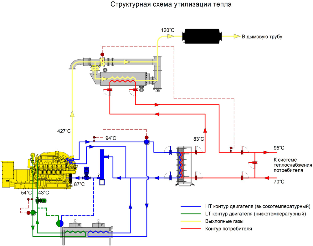
The main element TM are heat exchangers which transfer heat from engine coolant and exhaust gases to the water.
- Heat exchanger – the heat exchanger of the coolant – plate or shell and tube. Mainly used lamellar. If necessary – shell and tube.
- Heat exchanger – heat exchanger exhaust gas is a shell and tube heat exchanger with a tube sheet, specifically designed to use exhaust heat. Runs from black steel. For use in conjunction with a diesel engine are made of stainless steel.
In the structure of the company includes control valves and mechanisms, measuring instruments, automatic control system, heat insulating coating, load-bearing structures.
- To switch the exhaust gas flow uses two cranes and electric drive of the type MEO.
- To switch the flow of coolant or water used three-way valves with actuator. This valve is also used as a thermostat in the cooling circuit of the engine.
Insulation cover installed on piping and equipment operating at high temperatures.
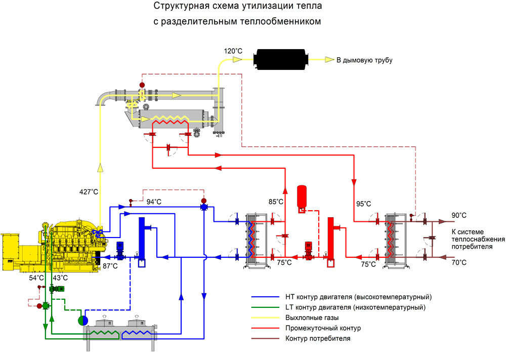
The composition of the TM if necessary, you can include additional equipment, such as circulation pump, additional heat exchanger (a dividing circuit or oil circuit), the muffler according to the customer.
FEATURES
Minimum aerodynamic resistance in the course of the exhaust gases allows to use in conjunction with long flues.
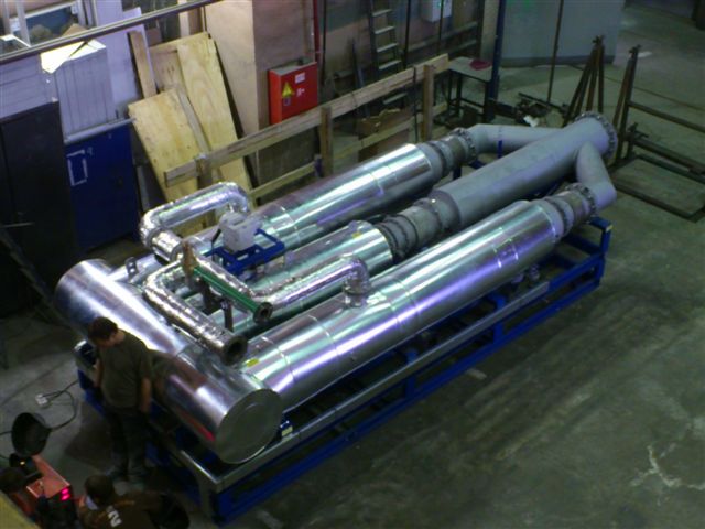
Compact placement of equipment in TM allows the use of relatively small space when placing TM in a container or in the engine room. Automatic control simplifies the operation.
Standard complectation:
- Frame thermal module.
- Heat exchanger exhaust:
2.1. Shell and tube heat exchanger (exhaust gas/water) of boiler steel.
2.2. The bypass compensator of thermal expansion.
2.3. Gas-valve with a pulling mechanism (switching of gas flow heat exchanger/bypass).
2.4. Electric gas valves (proportional regulation).
2.5. Collection of condensate with level sensors and solenoid valve for condensate drain.
2.6. Flanges for connecting inlet and outlet flue.
- The heat exchanger in high temperature cooling circuit.
3.1. Shell-and-tube (plate) heat exchanger antifreeze/water.
3.2. The three-way valve with electric proportional control (switch-coolant heat exchanger/emergency chiller).
3.3. Shut-off valves on pipelines antifreeze (inlet and exhaust piping).
3.4. Flanges for connection to external piping).
3.5. Temperature sensors and pressure at the outlet of the pipeline supply of antifreeze to the unit.
- The network circuit of the heat module (70/90 S).
4.1. Flanges for connection to external ductwork.
4.2. The bypass duct between the entrance and exit of the network path.
4.3. Shut-off valves on the input, output, and Bipasha the pipeline.
4.4. A filter at the inlet of the heat exchanger antifreeze/water.
4.5. Temperature sensors and pressure, flow switch network circuit.
- Insulation.
- Control Board thermal module.
Additional options:
- Shell and tube heat exchanger (exhaust gas/water) in stainless steel.
- Pump HT the contour of a master.
- Thermostat HT circuit.
- Pump LT the contour of the unit.
- Thermostat LT circuit.
- The pump power circuit.
- Expansion tanks HT and LT circuits.